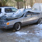
When it came time for inspection, the state of the exhaust of the Mont was in pretty sad shape (muffler holes, etc.) so I was pretty confident it wouldn’t pass. I figured I’d get to it eventually, patch it up, it’d pass and be back on the road. Well, after it sat for a month I decided to fire it up – it sounded horrible. There was an extremely loud engine knock, so I figured it had enough. Out it goes. Despite the anemic performance, it served me well for 25,000 or so miles.
Demise of the inline 6.
The LTD emerges.
Here is my list of needs that I would like to address to reach my goal of driving this to the Mustangs Unlimited show in Manchester, CT on April 26.
Needs:
– brake proportioning issue
– mount vac. res. deleted
– retorque trans pan
– reinstall visors
– wire horn
– hanger for exhaust at rear skipped
– swap back to off road h
– stock mustang h pipe swap
– cold dying issue resolved throttle stop screw
– Mustang shifter swap
– permanently mount interior wiring
– wipers
– put back interior pieces that are off
– front license plate bracket fabricated
– tail light bulb
– convoluted tubing
– new dipstick
– battery tray mustang
– shim ac delete bracket for better pulley alignment
– new serpentine belt 060733
– brakes: shoes & springs pads ok
– weld trans crossmember
– center console gauge mounting plate
– heater hoses
– timing, stumbling, running issue dist. stator, cracked plug, in tank pump
– timing cover gasket
– timing chain summit
– fuel filter
– door striker bushings 50resto
low priority:
– interior turn signal lights
– passenger door able to open from inside
– new beefier battery cables
– some rubber floormats
– battery hold down
– shifter cover of some sort
– ac condenser removal
– matching front seats would be nice
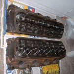
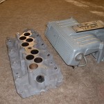
– replace top end parts with powdercoated ones so the engine’s not so ugly temporarily painted
Finally some attention for the neglected LTD.
Also, the roller block and all parts I was working on for the Mont will eventually be making their way into the LTD.
The bird blows a gasket!
This was about the only gasket I did not replace when putting in the new engine. Oops.
Tore the top end off the same day in the dark and could go no further because no place had head gaskets or bolts in stock. Cylinder 4 was steamed clean and there was a very obvious gasket break.
Got the gasket and bolts the next day after work and started in (with some help) on it again. The head and block looked ok (the cylinders actually look pretty nice still.) By about 9:30 it was back together and running but still puffing a lot of smoke. Crap. I thought maybe the head was cracked so I quit for the night.
With a little help from my friends at v6z24, I found that it could still be more in the exhaust (even though I had run it for a while, which surprised me – it could take up to a half hour to run it all out!) I cranked it with the plugs off to see if any were getting coolant filled. Then I ran it with the exhaust unhooked at the exhaust manifold and it was clean! No smoke! So needless to say I was pretty happy not to have to tear it apart again. It’s a bit of a pain.
So now we’re back on the road!
5.0 Throttle Body Disassembly / Powdercoating.
Required for powdercoating a throttle body, as the throttle shaft bearings would be ruined if not removed.
General Disassembly:
Obviously, the throttle body has to be removed from the car first. Consult a Haynes or Chiltons if this is a problem for you…
Remove the TPS (throttle position sensor) from the housing by removing the two bolts. Pull the TPS away from the housing.
Remove the two (phillips head) screws from the throttle blade, apply pressure and be careful to not strip the heads.
Once they are removed the blade will come out, as will the shaft from the linkage end.
If powdercoating or painting, you may want to remove the throttle stop screw and spring – but first measure the distance from the flange to the end of the bolt so you can replace it in the same position.
You are now left with the bearings.
Building the Tool:
You will need:
* a piece of 3/8 (.375) aluminum rod, maybe about an inch long – the length is not especially important
* approximately 4 inches of 3/8 rod, or anything of that length to fit through a .390 hole rigid enough to withstand a little pounding
* under .750 (3/4) rod, socket, etc.
* 8-32 flat head screw 1/2 or 5/8 – length not critical
* 82 degree countersink tool
* 8-32 tap
* #29 drill for tap
* hack saw or similar
Drill through the center of the 1″ long alum. piece with the #29 drill, then countersink to the edges (or close,) and then tap the hole. Saw down the center of the alum. about halfway, (.5 or .6 deep) enough to allow it to spread easily. That’s it for the tool.
Removing the Bearings:
First tighten the screw into the tool so that it won’t slide through the bearing. The idea is you will be spreading it enough so that it will catch and pull and not slip through as you use the 4″ 3/8 rod to pound the bearing out from the opposite side. It may take a couple tries to get the tool to the right size. Once it does, it should pop out and you can repeat for the other side and you’re ready for powdercoating or paint. See the diagram for a visual aid.
Reassembling:
If you’re powdercoating, remember to mask to avoid coating gasket surfaces, threaded holes, and especially the bearing holes. If you already powdercoated your threaded holes, you can retap them to clean out the powder with an M4x.7 for the TPS and an M5x.8 for the throttle stop. The OD of the bearings is about .750 or 3/4 so you will need something slightly smaller to tap the bearings back into place until they bottom out. The more area you have, the better – as long as you’re not pounding just on one part (the inner, central, or outer portion) of the bearing but on as much of all three as possible, it should work fine. You could potentially damage them if you’re not careful. Replace the throttle stop, setting it to the measurement you recorded earlier, and then the rest is just putting back what you removed.
Ford Motorsport Multiport EFI Engine Management Harness.
Download the Ford Motorsport EFI Wiring Manual.
or view individual pages:
1 – table of contents, intro, overview
2 – component list
3 – component list, general installation instructions
4 – engine (injector) harness wire colors & connections
5 – engine (inj.) harness connection locations
6 – main & hego (o2) harness wire colors & connections
7 – main harness connection locations
8 – o2 harness connection locations
9 – tools, sensors & relays, engine (inj.) harness install
10 – engine (inj.) harness install
11 – engine (inj.) harness install
12 – engine (inj.) harness install
13 – main harness install, firewall hole pattern
14 – main harness install, firewall hole pattern, eec mount
15 – main harness install, brown splice
16 – main harness install, green splice
17 – green & brown connector diagram
18 – main harness install, hego/o2 install
19 – main harness install, hego/o2 install
20 – cautions, notes, grounds
21 – fuel system
22 – vacuum diagram
23 – startup, troubleshooting
24 – troubleshooting, general info
25 – misc. parts list and numbers
green brown – color coded splicing guide for the green and brown connectors
In progress: manual retyped for legibility and non-image-based pages – pdf files.
Engine Bay Prep.
Megasquirt!
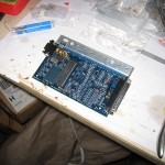
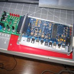
2/15/09 A formerly unassembled Megasquirt v1 pcb3.0 from diyautotune is now completed and functional. I’ll be using an EEC-IV adapter board for zero rewiring, which only needs a few jumpers to be complete. All I need now is a relay cable and to read up more on Megatune.

